Control Flow and Data Flow Graph
Control Flow Graph (CFG)
Overview
A Control Flow Graph (CFG) 是程序计算和控制流的图表示。用于建模程序的执行路径,是静态分析的核心。
Structure of a CFG
The structure of a Control Flow Graph consists of two main components:
- Nodes(computation): 令每个节点表示一个basic block. basic block 要么是一行代码或者几行可连续执行的代码,满足:
- 单一的进入点(single entry point,no branching except at the beginning or end).
- 在块中无跳转和分支(i.e., it is a linear sequence of instructions).
- Edges(control flow): 表示块间可能的控制流:
- 块尾到另一块首的边表明程序执行时潜在的转移路径
- 块可能有多个入边和出边(e.g., loops, conditionals, or function calls).
Basic block
连续语句序列,满足:
- 控制流只在序列首进入
- 控制流只在序列尾离开
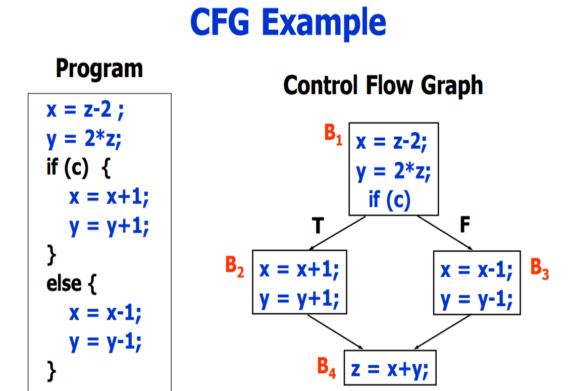
CFG Example:
可能的执行路径为图中的path
Execution 1
B1->B2->B4
Execution 2
B1->B3->B4
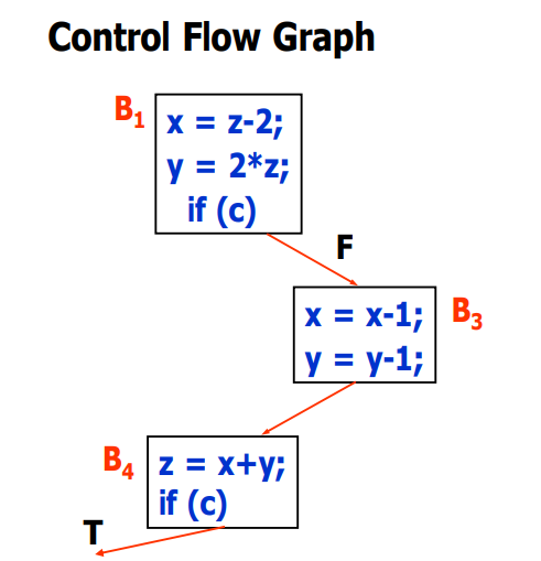
Infeasible executions
控制流图(CFG)表示程序的所有可能执行路径,包括那些在实际运行中永远不会被触发的路径。这些路径称为“不可能执行路径(Infeasible Executions)
Build CFG for high-level IR
工具1 clang
clang:LLVM的C/C++前端,能够生成抽象语法树(AST)和IR,从而生成控制流图。 用法示例: 可以通过使用LLVM的 -fdump-tree-cfg 选项来生成C++程序的控制流图:
1
clang -fdump-tree-cfg my_program.cpp
工具2 clang Static Analyzer
1
clang --analyze my_program.cpp
数据流图(data flow graph, DFG)
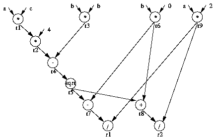
图数据流图(DFG,Data Flow Graph)是一种图形化表示,用于描述程序中数据之间的流动和依赖关系。每个节点通常表示一个操作或计算,每条边表示数据的流动和依赖。
1
2
3
4
5
6
7
8
9
10
11
12
quad( a, b, c)
t1 = a*c;
t2 = 4*t1;
t3 = b*b;
t4 = t3 - t2;
t5 = sqrt( t4);
t6 = -b;
t7 = t6 - t5;
t8 = t7 + t5;
t9 = 2*a;
r1 = t7/t9;
r2 = t8/t9;
参考文献
This post is licensed under CC BY 4.0 by the author.


